
Multipoint Locks: What to Measure, from Backset to Hook Positions
A multipoint lock is measured in six steps: backset, center distance, faceplate length and width, gearbox position, every locking point from the spindle center, and spindle size. On UK uPVC and composite doors 35 mm or 45 mm backsets and a 92 mm center distance are common, but they are starting points to check. We do not list multipoint locks; this is the method, plus the cylinder and lever details that go with it.

Johnson LiuDigital Communications, Canton HylandMA Digital Media, Johns Hopkins University
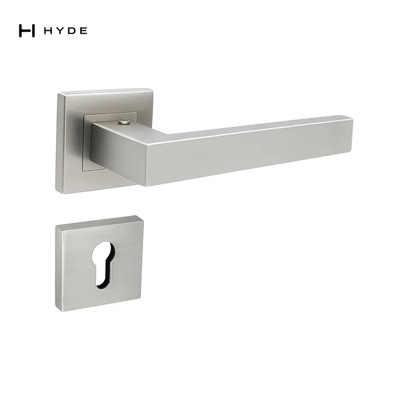
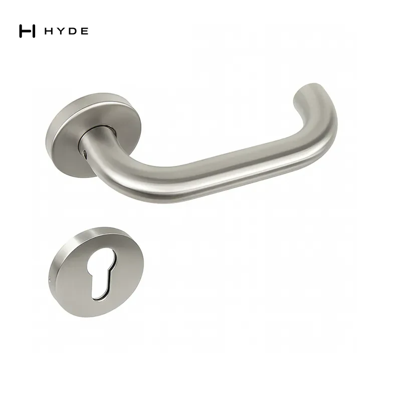
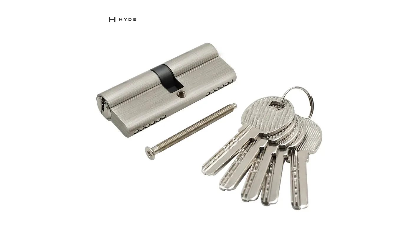
To replace a multipoint lock, measure six things in this order: backset, center distance (PZ), faceplate length and width, gearbox position, the position of every hook, roller and bolt measured from one datum, and the spindle size. On UK uPVC and composite doors the backset is most often 35 mm or 45 mm and the center distance most often 92 mm, but those are values to check on the door, not values to assume.
We should say at the start that we do not list multipoint locks. Our lock cases are single-case mortise locks; even LC14, which throws four round bolts, does it from one case, which makes it a multi-bolt lock rather than a multipoint one. Our 320 Two Point Locking Exit Device is a push bar that engages the head and threshold, which is a different product again. What we do list are two parts every multipoint replacement still needs, the euro cylinder and the lever pair, so this page is the measuring method, written so that the lock you order from any supplier fits the door you already have.
Why a multipoint lock is measured differently
A single-point mortise lock is one case in one pocket. A multipoint lock is a gearbox in the middle of a long strip that runs most of the height of the door edge, with locking points above and below it. The gearbox dimensions decide whether the handle and cylinder line up with the holes already in the door. The strip dimensions decide whether the locking points meet the keeps on the frame.
A replacement can be right on the first and wrong on the second. The door then locks at the gearbox and nowhere else, or the hooks hit the frame and it does not lock at all. Backset and center distance are covered in our guide to reading mortise lock case numbers; this page takes them as known and spends its time on the strip, which is where most wrong multipoint orders come from.
The measuring order
Scroll sideways to compare columns. Select a column heading to sort; select it three times to restore source order.
| 1 | Backset | Face of the faceplate to the center of the spindle and cylinder | 35 mm and 45 mm are common in the UK; other sizes exist |
|---|---|---|---|
| 2 | Center distance (PZ) | Center of the spindle to the center of the cylinder | 92 mm is the most common on UK uPVC and composite doors; other sizes exist |
| 3 | Faceplate length and width | End to end along the edge; across the face; note flat or U-channel and the end shape | Set by the door system; measure, do not assume |
| 4 | Gearbox position | Spindle center to the top end and to the bottom end of the faceplate | Set by the door system |
| 5 | Hook, roller and bolt positions | Spindle center (the datum) to the center of each locking point, above and below | Set by the door system |
| 6 | Spindle size | Across the flats of the square | 8 mm is common on UK lever pairs; measure it |
6 rows · Source order
Write every figure in millimeters, and write next to each one whether you measured it on the door or copied it from a document. That one note tells the supplier which figures they can rely on.
Steps 1 and 2: backset and center distance, taken on the door
On a multipoint lock the spindle and the cylinder sit on one vertical line, so a single backset reading serves both: from the face of the faceplate to the center of the cylinder hole. Center distance is the vertical gap between the center of the spindle and the center of the cylinder. On most lever-operated gearboxes the spindle is above the cylinder, which is why the handle plate has its keyhole below the lever. A 92 mm center distance belongs to the gearbox, not to the door, and the handle has to match it. A backplate handle drilled for one center distance cannot be used on a gearbox with another, because the spindle and the cylinder will not both line up with it.
Step 3: faceplate length and width
Measure the faceplate end to end along the door edge and record it to the nearest millimeter. Then measure the width across the face and note the section: flat, or U-channel, which wraps the edge of a uPVC profile. Width and section belong to the door system. A faceplate narrower than the old one leaves part of the routed pocket exposed, and one that is wider does not go in. Note whether the ends are square or rounded, because the new plate has to sit in the same pocket.
Step 4: where the gearbox sits on the strip
The gearbox is not always in the middle of the strip. Measure from the center of the spindle up to the top end of the faceplate, and down to the bottom end. Those two figures, together with the overall length, fix where the handle sits on the door. A replacement with the same backset and center distance but the spindle higher or lower on the strip puts the new handle holes beside the old ones.
Step 5: every locking point, from one datum
List every locking point on the strip, top to bottom, and name each one: hook, roller, round bolt, mushroom cam, deadbolt, latch, or a shootbolt into the head or the sill. For each one, measure from the center of the spindle to the center of that point, and write above or below next to the figure.
The spindle center is the right datum because it is the one point the handle, the gearbox and the door preparation all share. Measuring from the end of the faceplate looks easier, but it carries any error in the overall length into every position. Some suppliers publish positions from the top of the faceplate instead; if their drawing does, convert your figures before you compare, or ask which datum the drawing uses.
Then measure the keeps on the frame the same way. With the door closed, mark the spindle height on the frame and measure each keep from that mark. The locking points have to meet the keeps as they are now, not as the old lock's description says they should be. On a door that has dropped or been adjusted, keeps are often moved, and the replacement has to suit where they are.
Step 6: spindle size and how the lock is operated
Measure the spindle across its flats with a caliper. An 8 mm square is common on UK lever pairs, and our 9004S and 9003E stainless steel levers both publish an 8mm spindle. At the same time, record how the lock is operated: lever lifted to throw the hooks, key turned to throw them, or locking automatically when the door closes. Those are different gearboxes, and a lever that is right in every dimension is still the wrong part on a gearbox that expects a fixed pull pad outside. Record the hinge side as well, because not every gearbox has a reversible latch.
One limit on our levers should be stated plainly. The 9004S and 9003E are rose levers, published for 35–50mm doors, not long backplate handles. A rose lever with a separate cylinder escutcheon does not fix a center distance, so it can suit a timber door with a multipoint gearbox where the face allows separate roses. On a uPVC door whose preparation needs a long backplate to cover it, it is the wrong handle. Some gearboxes also rely on the handle's own return spring; we do not publish a spring rating for these levers, so ask before pairing them with a gearbox that needs one.
The cylinder, which is the part most often ordered wrong
Cylinder length is not a lock dimension. It is set by the door thickness plus the handle plates on each side, and a euro cylinder is quoted from the center of its fixing screw hole to each end. Measure each side separately, from the screw center to the outer face of the handle plate, and add the two. A 70 mm cylinder split 35/35 is a different part from a 70 mm cylinder split 30/40, although both are 70 mm overall. On the outside, the cylinder should finish close to flush with the handle plate; one that stands well proud gives a tool something to grip.
Our 70 SNKT-2 shows why the split has to be written down. Its record publishes the split as 30 / 10 / 30mm, two 30mm ends with a 10mm cam section between them. Read to the center of the cam, which is how the market usually quotes it, that is 35/35. Our 70SN and 80SN publish an overall length of 70mm and 80mm and do not publish a split, so ask for it before ordering and do not assume either one is symmetrical.
What to send with an inquiry
Send the six figures in the order of the table, the datum you used, the list of locking points top to bottom, the operation type, the hinge side, the door material and thickness, and two photographs: the whole faceplate on the open door edge with a tape alongside it, and the gearbox area close up. Copy any maker's name or code stamped on the faceplate exactly. It does not replace the measurements, because ranges change and copies exist, but it tells the supplier which drawing to check them against. For the parts we do list, the published figures are the ones we would quote back to you: overall length on the euro cylinders, the split where it is published, and spindle size, rose size and door thickness range on the levers named above. Where a figure is not on a product page it is not published, and we will measure it before quoting rather than infer it.
Questions this answers
How do you measure a multipoint lock for replacement?
Measure six things in order: backset, center distance (PZ), faceplate length and width, gearbox position on the strip, the position of every hook, roller and bolt from the spindle center, and the spindle size. Then measure the keeps on the frame from the same spindle height, because the locking points have to meet the keeps where they are now.
What is the most common center distance and backset on a UK multipoint lock?
On UK uPVC and composite doors, 92 mm is the most common center distance, and 35 mm and 45 mm are the most common backsets. Other sizes exist, so measure the door rather than assume.
Where do you measure multipoint lock hook positions from?
From the center of the spindle to the center of each hook, roller or bolt, writing above or below next to each figure. The spindle center is the one point the handle, gearbox and door preparation share. If a supplier's drawing measures from the top of the faceplate, convert your figures before comparing.
How do I measure the euro cylinder on a multipoint door?
Measure each side from the center of the fixing screw hole to the outer face of the handle plate, and add the two. A 70 mm cylinder split 35/35 is a different part from one split 30/40. Our 70 SNKT-2 publishes its split as 30 / 10 / 30mm, which reads 35/35 to the center of the cam.
Does Canton Hyland sell multipoint locks?
No, we do not list multipoint locks. We list parts a multipoint replacement still needs: euro cylinders such as the 70SN and 80SN, and stainless steel rose levers such as the 9004S and 9003E, which publish an 8mm spindle.
Related products
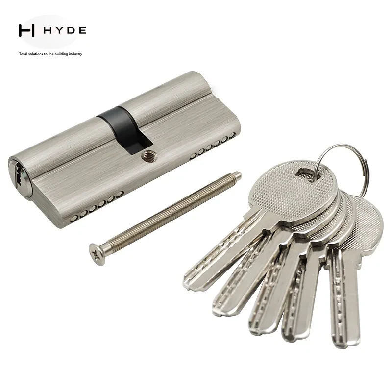
Size 80mm
Lock Cylinder
Model 80SN
Solid Brass
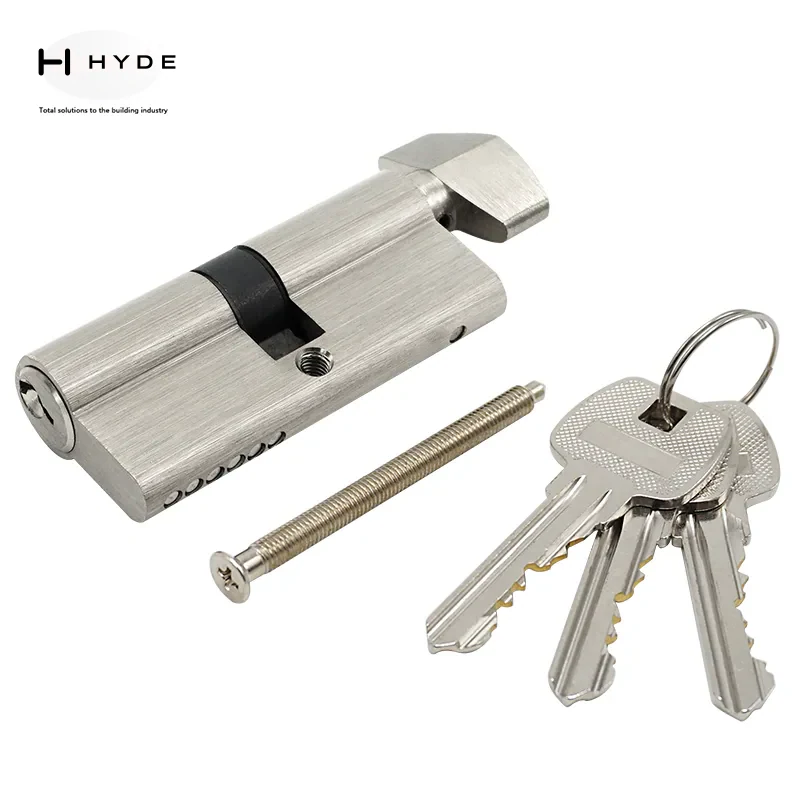
Size 70mm
Lock Cylinder
Model 70SN
Solid Brass
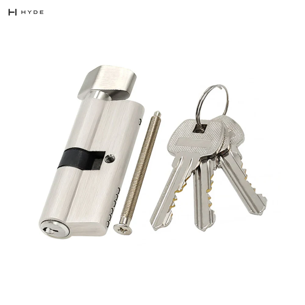
Size 70mm
Lock Cylinder
Model 70 SNKT-2
Solid Brass
About Canton Hyland — Canton Hyland manufactures panic exit devices, locks and architectural door hardware for commercial and institutional projects, supplying specifiers and distributors internationally.